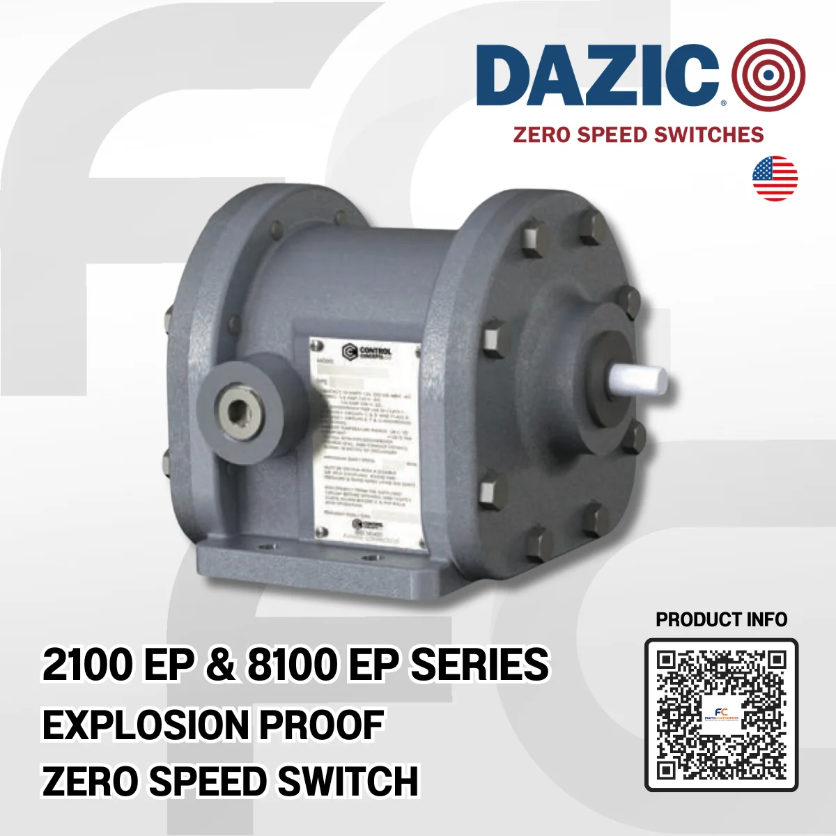
ข้อมูลจำเพาะทางเทคนิค (Technical Specification) ของ DAZIC® — EXPLOSION-PROOF ZERO SPEED SWITCHES
Operating Range: 2100 EP Series — 4 to 2000 RPM, 8100 EP Series — 0.5 to 25 RPM
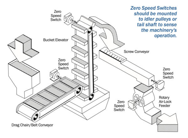
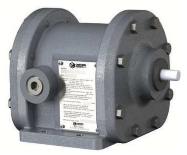
DAZIC® [ดาซิก/เดย์ซิค] เป็นแบรนด์ในไลน์ผลิตภัณฑ์ของ Control Concepts Inc. จากสหรัฐอเมริกา สวิตช์ความเร็ว DAZIC® Zero Speed Switches ซีรีส์ 2100 EP และ 8100 EP เป็นสวิตช์ควบคุมการเคลื่อนที่แบบหมุนด้วยเครื่องกลไฟฟ้าป้องกันการระเบิด สวิตช์ความเร็วเป็นศูนย์ทั้งสองรุ่นจะตรวจสอบการเคลื่อนที่แบบหมุนของอุปกรณ์เมื่อเชื่อมต่อกันโดยเป็นส่วนหนึ่งของระบบสายพานลำเลียง หรือส่วนประกอบกระบวนการที่ขับเคลื่อนด้วยเพลาอื่นๆ ในสถานที่อันตราย สวิตช์ควบคุมการเคลื่อนที่แบบหมุนด้วยเครื่องกลไฟฟ้าป้องกันการระเบิด ซีรีส์ DAZIC® 2100 EP และ 8100 EP จะตรวจสอบการเคลื่อนที่แบบหมุนของอุปกรณ์เมื่อเชื่อมต่อกันโดยเป็นส่วนหนึ่งของระบบสายพานลำเลียงหรือส่วนประกอบกระบวนการที่ขับเคลื่อนด้วยเพลาอื่นๆ ในสถานที่อันตราย หากไลน์หนึ่งมีการเบี่ยงเบน ทำงานผิดปกติหรือขัดข้อง สวิตช์จะ…
- ตัดวงจรเดินที่ไปยังมอเตอร์ (Break a circuit to a motor)
- ส่งสัญญาณหรือแจ้งเตือนภัย (Actuate a signal or alarm device)
- ส่งสัญญาณไปยังสถานีควบคุมหรือ PLC (Signal a control station or PLC)
- สร้างหรือตัดวงจรไปยังอุปกรณ์ไฟฟ้าอื่นๆ (Make or break a circuit to other electrical devices)
- สตาร์ทอุปกรณ์เสริมที่สามารถช่วยแก้หรือบรรเทาสถานการณ์ได้ (Make a circuit to start auxiliary equipment)
เมื่อถูกขับเคลื่อนจากเพลาวิกฤติ หรือ Critical Shaft สวิตช์จะทำงานเมื่อความเร็วการทำงานปกติของระบบ…
- หมุนกลับด้าน (Reverses rotation)
- เริ่มเร่งความเร็วเกินไป (Begins to overspeed)
- ช้าลงเนื่องจากการโอเวอร์โหลด (Slows down due to overload)
- หยุดทำงานเนื่องจากความล้มเหลวทางกลไก (Stops due to mechanical failure)
- เปลี่ยนแปลงเนื่องจากการหมุนเวียนของเครื่องจักรตามรอบปกติ (Changes due to normal machine cycling)
2100 EP and 8100 EP Series |
|
| Driver | Shaft-to-shaft |
| Shaft Diameter | 1/2″ (1.27 cm) |
| Driver Torque Required |
.0208 ft-lb (.0282 Nm) |
| Temperature Tolerance |
-40°F to +250°F -40°C to +121°C |
| Housing Options | Cast Aluminum |
| NEMA Rating | 7/9 |
| Mounting | Base mount |
| Dimensions L x W x H |
7.29″ x 6.55″ x 5.93″ (18.52 cm x 16.64 cm x 15.06 cm) |
| Wiring Contact Options |
SPDT, DPDT, SPDT(2) |
| Weight | 13 lbs. (5.9 kg) |
Operating Speeds:
- 2100 EP Series — 4 to 2000 RPM
- 8100 EP Series — 0.5 to 25 RPM
ข้อมูลจำเพาะสวิตช์ความเร็วเป็นศูนย์ป้องกันการระเบิด (Explosion-Proof Zero Speed Switches)
2100 EP Series — Explosion Proof Zero Speed Switches
Operating Speeds from 4 to 2000 RPM
Speed Switch Input (RPM)(Application Running |
Approximate Contact Operating Speeds (RPM) |
Contact Type |
|||||
MIN. RPM |
MAX. RPM |
Start-Up Trip-Point Upon Initial Speed Switch Acceleration (RPM) |
Drop-Out Point On Shaft Speed Loss (RPM) |
SPDTSingle Pole, Double Throw |
DPDTDouble Pole, |
SPDT(2)Direction |
|
| SLOW LOSS | RAPID LOSS | MODEL NO. | MODEL NO. | MODEL NO. | |||
| NOT FIELD ADJUSTABLE | |||||||
| 24 | 2000 | 14 to 10 | 10 | 0 | 2120 | 2122 | 2130 |
| 15 | 200 | 8 to 11 | Approx. 2 Sec. After Shaft Rotation Failure | 2120-1 | 2122-1 | 2130-1 | |
| 8 | 100 | 5 to 7 | Approx. 3 Sec. After Shaft Rotation Failure | 2120-5 | 2122-5 | 2130-5 | |
| 4 | 50 | 2 to 3 | Approx. 5 Sec. After Shaft Rotation Failure | 2120-10 | 2122-10 | 2130-10 | |
| FIELD ADJUSTABLE | |||||||
| 30 | 2000 | 25 to 70 | 30-40% Below Trip Point | 0 | 2120-A1 | 2122-A1 | 2130-A1 |
| 75 | 2000 | 60 to 140 | 30-40% Below Trip Point | 0 | 2120-A2 | 2122-A2 | 2130-A2 |
| 150 | 2000 | 125 to 450 | 30-40% Below Trip Point | 0 | 2120-A3 | 2122-A3 | 2130-A3 |
| 240 | 2000 | 200 to 600 | 30-40% Below Trip Point | 0 | 2120-A4 | 2122-A4 | 2130-A4 |
| 15 | 200 | 10 to 45 | 30-40% Below Trip Point | 0 | 2120-A11 | 2122-A11 | 2130-A11 |
| 7 | 100 | 5 to 15 | 30-40% Below Trip Point | 0 | 2120-A15 | 2122-A15 | 2130-A15 |
8100 EP Series — Explosion Proof Zero Speed Switches
Operating Speeds from 0.5 to 25 RPM
Speed Switch Input (RPM)(Application Running |
Approximate Contact Operating Speeds (RPM) |
Contact Type |
|||||
MIN. RPM |
MAX. RPM |
Start-Up Trip-Point Upon Initial Speed Switch Acceleration (RPM) |
Drop-Out Point On Shaft Speed Loss (RPM) |
SPDTSingle Pole, Double Throw |
DPDTDouble Pole, |
SPDT(2)Direction |
|
| SLOW LOSS | RAPID LOSS | MODEL NO. | MODEL NO. | MODEL NO. | |||
| 1.5 | 5 | 1.5 | 0.5 | 0 | 8121 | 81212 | 8131 |
| 0.5 | 25 | 0.5 | Approx. 4 Sec. After Shaft Rotation Failure | 8121-5 | 81212-5 | 8131-5 | |
| 2 | 25 | 1.5 | Approx. 3-5 Sec. After Shaft Rotation Failure | 8122-5 | 81222-5 | 8132-5 | |
*ไม่สามารถทําการปรับ ณ ภาคสนามหรือหน้างานได้ (Not Field Adjustable)


